RICHARD TURNER CLUTCH MOD
( On TheBeam September / October 1993 )
Hello Beamers,
This little mod has two advantages over the standard Beam clutch mechanism : ---
The extreme bend of the Bowden cable preceeding its' passage through the gaerbox lug is vastly reduced , hence less inner cable friction .
The machanical advantage of approx 2:1 results in half the requisite operative load at the lever .
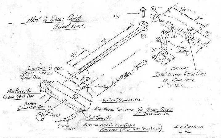
Please note that the dimensions that I have given are those taken from my Beam .I therefore suspect that , dependant upon the condition of the clutch, the length of the rod C and the length of clutch lever contacting lobe on A , may vary a bit , I think the design capable of accomodating all adjustment necessary .
The sketch is fairly self explanatory , if you assume original positions of clutch arm F and existing clutch cable lug on the gearbox and relate the position of everything else to them . Be a little wary of part E and its' slight restrictive access to the toolbox lid , but does not render it inaccessible , the bottom edge and distance from the centre line of the three holes to this edge must be minimal . I case hardened the lobe of part A in order that " the rocking friction generated during lever articulation " would'nt clap it out . ( Nice , eh )
ASSEMBLY AND FITTING
Part E is bolted ( 5/16 BSF ) to the original gearbox clutch cable lug . The clutch cable passes through E . Screw cable adjuster right home into E . Release the lever end of the cable and locate the other end nipple in D , which in turn pivots via a pin on part A .
Part C is offered through part E with a nut and washer each side , these nuts are then adjusted until lever A becomes square-ish to the to the axis of movement of the clutch lever . Assemble the lever end of the cable .
This , at least on my bike , then required a small amount of adjustment of the cable adjuster in E and - hey presto !!
Richard Turner
NB If it does not work on your Beam --- you can always throw it away without having modified yours from standard .
NOTES
This is brilliant --- I wish I had thought of it --- and has become widely spread throughout the Fellowship , you can almost tell if a Beam is ridden seriously by whether or not it has this mod .
The only comments that I can add are :---
That part C is easiest made from a length of Ľ" stainless and a rear brake rod clevis .
Fit both the nuts on part C to the front of part E , this allows the link system to take up its own best position .
If you make part A from 6mm steel the lobe is a better fit in the clutch lever.
I call my S7/Fiat special the "Phoenix" because it arose from the wreckage of a bent Sunbeam and a wrecked Fiat "Uno". The bike uses the 999cc F.I,R.E.( Fully Integrated Robotised Engine ) from the car , so it all seems to hang together .
The first question I usually get asked is why did I build it anyway ?? Well , it started out as a perfectly standard S7, built up from autojumble parts , and had almost reached the stage of final assembly. However due to work and other commitments , the whole project was shelved for about 18 months .
Towards the end of this time , my brother gave me an American calender showing prototype motorcycles , one of which was theIndian/Torque Lightweight Four . This was designed in 1943 by the Torque Engineering Co., but only built after a takeover by Indian . As soon as I saw this picture (below) I was immediately struck by how much it resembled a four-cylinder Sunbeam .
This inspired me to build a "replica" but with a water cooled engine to over- come the problem of cooling the rear cylinders .
I did not have to search very far for a suitable engine as my wife had a Fiat "Uno" 45 with the F.I.R.E. . This extremely good engine has been used in several Fiat and Lancia cars , moreover the general layout is very much the same as a four cylinder Sunbeam would be , with a single overhead camshaft , distributor to the rear , and the same bore and stroke .
By measuring the actual engine and scaling off the two very good section drawings in the Haynes manual, I convinced myself that this was a feasable project and went looking for a suitable engine - and no , I didn't steal steal the one out of my wife's car !!!
" "
A low mileage engine from a wreck was puchased at a cost of Ł85 , complete with alternator , and turned out to be barely run in .
The first task was to fit the engine to the Sunbeam gearbox , thus retaining the foot gear-change , kick-starting , and the basic location in the rear of the frame .
I was fortunate at the time to have access to a vertical miller with digital read-outs , which made producing the ˝ inch Dural adaptor plate much easier and more accurate . The centre of the plate was machined to carry the rear crankshaft oil-seal whilst the rear of the pressed steel sump was cut off and a vertical flange welded on , this was then bolted to the front of the adaptor plate .
This marriage of engine and gearbox was obviously meant to be , as the four engine and five gearbox bolts were almost equally spaced around the plate , whereas they could have been on top of each other which would have been most awkward . Also , lengthwise , the Fiat flywheel- Sunbeam clutch dimensions worked out to within 2mm , if I had used 10mm plate for the adaptor things would have been spot-on .
I am often asked why I did not fit the electric starter . For one thing by the time the Fiat flywheel had been reduced in diameter to fit the Sunbeam bell-housing , the starter ring was long gone and for another , apart from the starter you have to fit a car-sized battery . Finally I recalled that I had no problems kick-starting the "Square Four" that I once owned .
Attention was now focussed on the frame . So as not to cut up a perfectly good one I traded it to Stewarts for another that had been in a crash . The complete front of the frame was cut off , the top tube behind the steering head and the bottom tubes at the start of the upward curve . The rear of the frame plus the engine/gearbox were then propped up on a temporary jig , located together by the rear gearbox mounting . The top tube was extended by 4" with a newly machined headstock , this enabled me to fit the front wheel and forks to check operating clearences . These being satisfactory the the forks were removed and the front of the frame was rebuilt around the engine , including a fully braced steering head and built-in crash bars . In view of the extra weight of the engine I fitted S.R.M. taper roller steering head bearings .
So far , so good , but when the engine/gearbox was removed , the frame looked so long and open that I became concerned about it's torsional strength , the engine/ gearbox was replaced and a pair of bracing tubes fitted in line with the bell-housing . There are four mounting points for the engine/gearbox , one on each side attached to the adaptor plate , the standard one under the gearbox and another at the front of the engine about 12" up the R/H down tube .
To remove the engine/gearbox , the front mounting bracket is dismantled which allows the whole assembly to tilt forwards far enough for the gearbox to be slid off backwards , the engine may then be removed sideways .
When I first got the bike on it's wheels for real it looked most odd - all down at the front , then I realised that because the steering head was 4" forward , due to the angle of the top tube , it had also gone up about 1˝" , so I needed longer forks . This was achieved by screwing 2" extension pieces into the lower ends of the stanchions , then fitting S8 springs and spacers until the frame was level . The extension pieces contained the valves for the damping system . An advantage of all this is that the extra height offsets to some extent the increased length of the bike .
In order to retain the Sunbeam-like appearance as much as possible and also keep the the extra frame length to a minimum , the Fiat radiator is fitted into the R/H pannier . In this respect things once again worked out well , both the water connections on the engine are to the rear , whilst both of those on the radiator are at the front and there is also a built in header tank . This minimises the problems of making a neat and unobtrusive set of water pipes .The cooling system works very well in all normal circumstances and is fitted with an electric fan for slow riding in heavy traffic .
When I first rode the bike it was obvious that top gear was too low . To correct this I had a local engineering firm make me a new pair of gears ( 3 teeth off the layshaft , 3 teeth on the input shaft . This gave a top gear of 4.5:1 , the same as a Square Four , which seems about right since I don't keep going for another gear .
Obviously with this amount of grunt ( 50 BHP ) a Sunbeam rear drive would not last very long , so the spiral bevel drive from a 650cc Russian Dnieper flat twin is fitted , this conversion is one that I first used several years ago and is well tested .
Likewise this thing takes a bit of stopping so the so the front brake is an 8" full width twin-leading-shoe also from the Dnieper .
Using the standard Fiat alternator , distributor and carburettor kept things as simple as possible and has worked out well , the bike has always been an easy starter and totally reliable , the longest journey to date is 550 miles over this Easter weekend to a Sunbeam Rally in south Wales .
Riding the "Phoenix" is great and certainly justifies the effort , it is very smooth at all speeds and accelerates well , only being let down by the slow gearchange ( I am presently trying to devise some form of synchromesh ) . When I went down to Brooklands last year I was cruising on the M4 at 65 to 70 MPH with bursts up to 85 when overtaking , at this the fuel consumption was 62 MPG .
There are only two drawbacks that I have found in 3 years riding , one is the poor ground clearence which is why the exhaust system is now on the left to allow a redesign of the sump . The other is that wherever you go if you don't park it and walk away quickly , you are soon the centre of an interested crowd , and getting away can take quite some time , but then any Sunbeam is a great conversation starter.
I can't claim any credit for the design --- as far as I know Fiddler Fred was the first to do a mod of this sort (although on his bike the filter is outside of the engine) , and my brother adapted the idea to make the system I now use , with the filter inside the sump .
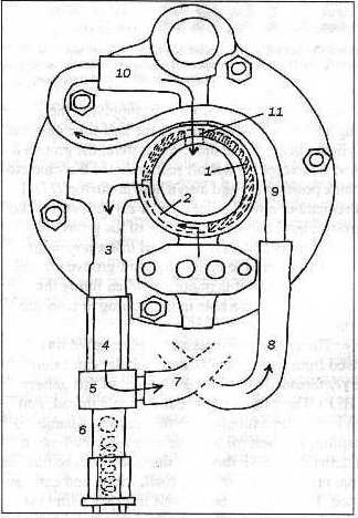
Following the numbers on the drawing this is how the mod works . Oil from the oil pump originally flowed around the outside of the rear main bearing by an annular groove , supplying the bearing and travelling upwards to the half-time gaer and the cylinder head . In the modified system , the groove is blocked (1) except for a short section in the 6 o'clock to 9 o'clock position (2) and also a hole at the top (11) .I can't remember how Fiddler Fred or my brother blocked the groove , but I had the front edge of the groove removed entirely and a circular steel insert pressed in . The insert is relieved to create the short groove (2) and drilled for hole (11 ). It is important when fitting the main bearing to get the hole in the bearing to coincide with the hole (11) .
The original oil-pressure release valve was removed from its gallery (3) and a tubular extension piece (4) threaded to fit into the bottom of this gallery ( 5/8 BSF ) . The bottom of (4) has a female thread into which is inserted a tubular bolt (6) securing a banjo (5) in position . The bolt (6) has a seating machined into it and a female 5/8 BSF thread at the lower end , so that the original pressure-release valve ( ball spring and nut ) can be fitted . The oil ( 15W-50 ) travels from the pump via the short groove (2) down to the banjo .
From the banjo a short length of flexible hose (7) runs forward below the crankshaft to a filter head mounted on a plate sandwiched between the sump spacer and the crankcase--- the sump is extended in depth bu about 7/8" by using a Stewart Engineering sump spacer kit . The filter head has a 16 by 1.5 mm thread , so that it can take a cartridge from a Citroen 2CV--- this is short enough to fit inside the extended sump . Filter heads of this type are readily available from motor factors , etc ., but my brother used a diesel fuel filter head which he modified . The oil returns from the filter to the rear main bearing carrier via another piece of flexible hose (8) . Flexible hoses are needed so the system can be assembled and dismantled easily , and it is of course important to use a grade capable of withstanding the oil temperature and pressure .
The oil then travels via a piece of copper tube (3/8 O.D.) (9) to the gallery (10) on the left of the half-time gear spindle . The original threaded blanking plug was removed from the gallery , the threads drilled out and the tube secured with epoxy resin . From here the oil can feed through the hole (11) to the rear main bearing and the rest of the crankshaft , and also to the cylinder head and the half-time spindle .A bracket ( not shown ) fixes the copper tube to the middle right stud securing the carrier to the crankcase.
Although the oil is now filtered an oil strainer on the pickup is still needed to protect the pump , I modified one from a car engine .
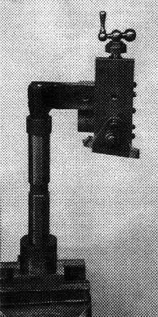
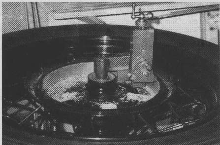
Having experienced poor performance and varying degrees of brake snatch on my S7 and S8 , I have recently completed a trueing device which can restore a drum to pristine condition in 30 minutes . Hand spinning the complete wheel in a bench vice is all the effort required .
" "
As can be seen from the photographs , the device consists of a spindle ( 7/8" diameter ) and bottom nut which will lock through the wheel bearing assembly , the nut being held in a bench vice . The top of the spindle has a plate welded or bolted to it , and attached to the plate is a small lathe top slide to provide the means for feeding a lathe tool across the drum surface .
In use a high speed steel tool ( a carbide tool is not necessary ) is set to take a 0.002"/ 0.003"cut . Checking the drum run-out with a dial indicator will show the high and low spots and the tool can be set accordingly to the run-out readings .
Spinning the wheel by hand and feeding the tool slide down about 0.005" at a time will soon make short work of the high spots . A knife edge tool with a small nose radius will give a good finish , and a final rub with fine emery cloth . Speed is not critical , but a wheel fitted with a tyre helps the spinning momentum .
Assuming the wheel bearings are in good condition an accuracy within 0.001"can be expected .The final result when fitted to the front of the S7 was impressively smooth and progressive .
Of the three wheels I have measured , there has been between 0.005" and 0.015" out-of-round prior to giving them the treatment !!
Dick Castle
NOTES
This is another cracking idea that I wish I had thought of --- when I was building the " Phoenix " , the " Dnieper " hubs were both badly out of round due to corrosion behind the liners . Snatch with a twin leading shoe brake is quite something , believe you me !!!
Using this device would have saved a lot of time and aggravation removing the tyres , stripping the wheels , skimming the hubs and rebuilding . Nowadays I check the roundness of brake drums before doing anything else !!!
Most importantly if re-building a wheel , before you take it to pieces carefully measure the position of the rim relative to the face of the brake drum , doing this will save you a lot of grief later . Taking a couple of photographs at this stage will also help later on , be close in so that you can see the details .
You do not need a building jig , clamp the wheel spindle upright in the vise and drop the hub on it with the brake at the bottom . Building a wheel on the flat is far easier because you can fan the spokes out into roughly their position and they stay there , this makes it much more obvious which spoke goes in which hole in the rim .
The next thing you have to do is sort out the spokes because all spokes are not born equal . Obviously with a single sided brake you will have two different lengths , these are further sub-divided into inners and outers . If you examine the bends at the end of the spokes , those with somewhat longer and more acute bends are the outer spokes because they have to wrap further round the spoke flange in order to point towards the centre of the rim ( think about it ) . Even with a full width hub this will still apply .
Having sorted out the spokes , GREASE THE THREADS , firstly to stop the nipples picking up on the threads thus making it difficult to tension them uniformly , secondly to prevent corrosion .
If you are dealing with a second hand hub , careful examination of the spoke holes will show you which way the spokes originally went because the pull of the spokes will have rounded off one side of the holes . If you cannot determine this do not worry as wheels have considerable symmetry and it all works out in the end .
With most hubs you have to put all the inner spokes into place and fan them out round the wheel before you start building , this is because once you get a few spokes into place they prevent subsequent ones from moving to their correct positions . Note that the spokes on opposite sides of the hub will be rotated opposite ways when viewed from the top .
The outer spokes are no problem because they are out in the fresh air . Sometimes you will come across a hub where you must put ALL the spokes into place before building , whilst others with a keyhole slotted flange you only need to put the brake side inners into place .
Now for the tricky bit where building it on the flat makes life so much easier . Get your mate to hold the rim level with the hub and central to it . Put a couple of OUTER spokes in place on opposite sides of the hub at the top , so that you have two pairs of inners and outers . Now by crossing these pairs over towards the rim it is usually pretty obvious which holes they have to go in , taking account of the offset of the holes in the dimples . Once you have got these two pairs of spokes connected up they will support the rim well enough for you to spin it and see if it is reasonably central .
If this is so , carry on adding outer spokes and connecting inners until the wheel is fully built , keeping an eye on the inners so they do not become trapped . Towards the end you may have to ondo a few spokes to sort this out . While doing all this only screw the nipples on a couple of turns as it helps to have the wheel as floppy as possible .
After fitting all the upper spokes and starting on the lower ones , you may find that the first one you try is nowhere near the obvious hole . In that case sweep all the inner spokes round in the opposite direction and try again , things should now line up .
Having got everything into place go round and tighten all the nipples to the bottom of the threads , the wheel should be now starting to stiffen up and run true . By going round the wheel and tightening all the nipples by reducing increments get the rim running round and flat . I use a scribing block sat on the bench top as a sighting device but any thing will do , I once used a bit of welding rod stapled to a block of wood . Any out of round and wobble will have to be pulled out by careful tightening and loosening of the spokes , bearing in mind that at the end all the spokes must be equally tight .This can be checked by striking them and listening for a nice crisp note , excessively tight spokes are just as bad as loose ones . At about this time you need to turn the wheel over so that you can check the position of the rim relative to the brake plate before final tightening of the nipples . I aim to get the rim to run true to within a couple of millimetres , however with a Sunbeam I have found that it pays to be as true as possible . Smooth wobbles in the rim can usually be pulled out but kinks cannot .
If the position of the rim is not known , place the wheel into the front forks or rear of the frame and set it central by measurement , being careful with the rear wheel because frames are not always symmetrical about the centre line . If all else fails take the mudguard off and sight down the length of the frame .
Finally carefully examine the wheel to make sure that none of the spokes are standing proud and grind off any that are , don’t forget the rim tape .
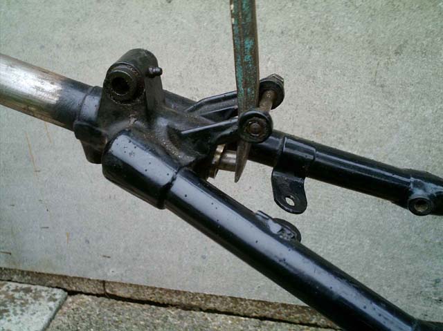
Any one who has tried to assemble an S7 Saddle will know how difficult it is to compress the spring far enough for the rear pivot bolt to be inserted without damage .
I well recall the struggle I had with mine when I built the Phoenix , so this time round I decided to make some proper tools to do the job in ease and comfort .
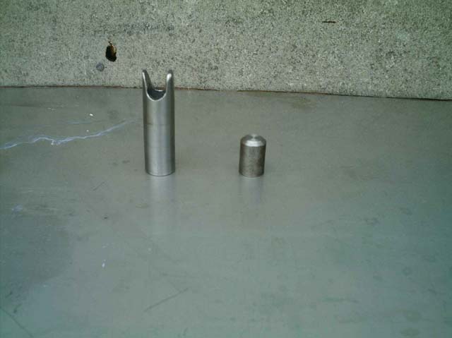
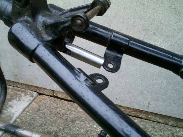
What I eventually came up with is two simple pieces easily made from scrap , the first is a 16mm diameter , 24mm long plug which fits into the back of the spring and enables one to compress it into the frame using a small crowbar and the rear pivot bolt as a fulcrum .
The second is made from a piece of thick walled 19mm tubing with the end slotted so as to fit into the frame against the spring and secured by butting up against one of the frame lugs which support the electrical boxes . In my case this part was 64mm long but this may vary a bit with different frames , as may the shape of the slot to fit the spring opening .
If you get the length right it will retain the compressed spring just far enough in when you remove the crowbar to allow the saddle to be assembled without having to force anything , the tube is simply removed after assembly by pushing the saddle down .
Obviously reversing this sequence allows one to dismantle the saddle just as easily .
Having become rather fed up of snatchy front brakes on both my Sunbeams , I finally decided to do something about it .
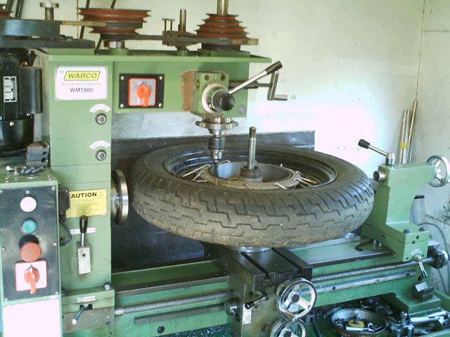
I was all set to make the device suggested by Dick Castle in OTB Nov/Dec 2000 , which consists of a dummy wheel spindle with a small lathe cross-slide attached , when I realised that I could use the facilities of my combined lathe and miller .
This is a Warco WMT800 , the largest model that they make and in my opinion the only one worth buying because it’s size makes it so versatile .
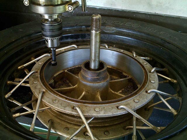
Firstly I removed the lathe chuck and the compound slide assembly and then bolted the three jaw chuck from my dividing head to the cross slide . A wheel spindle was then clamped in place and the wheel dropped on complete with tyre and tube .
A normal lathe boring tool was then fitted into a chuck in the milling head which was prevented from rotating by a couple of toolmakers clamps on the main pulley .
Now by spinning the wheel and symultaneously feeding down the milling spindle it was possible to skim the drum in a properly controlled manner , the cut being applied by moving the cross slide .
Spinning and feeding at the same time is a bit tricky but you soon get used to it , if I was to do this very often I would rig up a small electric motor with a friction drive on the tyre .
It did occur to me that I could have used a small grindstone with the milling head running to finish the job off , but the bored finish was pretty good and the drum was running true .
This operation was totally successful on both S7 and S8 wheels and the beauty of it is that this method could be done on any fairly large milling machine .
When first plotting a swinging arm Sunbeam the obvious starting point seemed to be a Dneiper frame , since I was already using a modified Dneiper rear drive which would bolt straight in if returned to standard .
On obtaining a frame it was immediately obvious that it was too narrow at the bottom and not deep enough to take the much taller Sunbeam engine .
In the finish I only used the swinging arm and its support tubes . I realised that if these supports were exchanged side for side , then the offset of the mountings would move the tubes out to just a little wider than the bottom of a Sunbeam frame , which seemed too good a starting point to ignore .
After managing to find an S8 frame that some vandal had cut off one of the rear suspension assemblies , I then cut off the other one and also cut the top tube just in front of the seat mounting . The bottom frame lug which carries the centre stand was also removed but without cutting the frame .
This stripped frame was then set up on a building jig that I had made for another project , located by the front forks which were jacked up to full extension .
The engine and gearbox were put into place so that I could work out the lengthwise location of the swinging arm . It then became obvious that in order to have the swinging arm pivot at the correct height , the back of the gearbox needed raising up . This was done by pivoting the engine about the bottom front snubbers ( these being fixed points both in the engine and on the frame ) . It was achieved by moving the plate which carries the “Cobra” from the back to the front of the frame lugs thus causing the gear box to move up in the frame by about 2 inches .
The bottom frame tubes were sprung apart to line up with the support tubes and a cross tube welded in place , this tube carries a new mounting for the gearbox .
The top snubber fitted by simply sliding it forwards along the top tube .
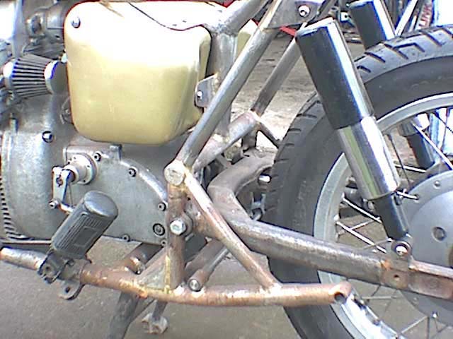
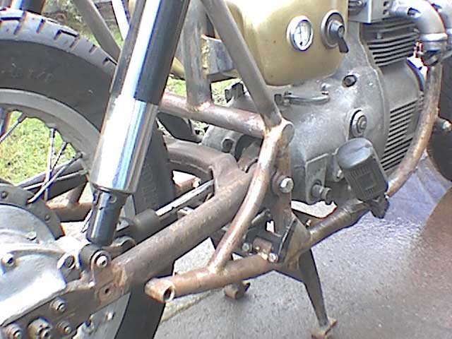
Then to connect the two ends of the frame , the swinging arm support tubes were fitted in place and welded at the meeting points of the frame and cross tube . This was then made very rigid by extending the frame top tube backwards and down to another cross tube above the swinging arm , further triangulated by a pair of tubes back towards the pillion footrest mountings .
A third cross tube was fitted forwards of the gearbox mounting to further stiffen the bottom of the frame and to carry the centre stand more nearly at the centre of balance of the whole bike .
The prop-shaft has a Sunbeam universal joint at the front , a Dneiper one at the rear and passes through an opening in the forward cross member of the swinging arm . This minimises movement at the sliding joint but does mean that every thing must be lined up very carefully to avoid contact between the shaft and the arm .
At this point in the build I ran into trouble when I tacked up a sub-frame and then tried to fit the dual seat , but these modern plastic based seats cannot be supported at the two ends like a BSA one . I had to reverse the process by making a steel loop to closely fit the seat and then build this into the frame . Once I adopted this method the rear end of the frame was quickly finished , the spring units being a standard pair of Girlings as fitted to most of the heavier British bikes .
While laying out the frame the whole bike was jacked up by about 2 inches , partly to allow for the extra suspension also to get the swinging arm to lie correctly . The front forks have extension pieces screwed into the bottom of the stanchions , these pieces carry the valves for the two-way damping .
A BSA C15 prop stand looks the part and is just the right amount longer .
The electrical boxes are mounted in a similar way to on a Beam but spaced apart by the width of the frame top tube . Since the front of the seat is wider than a saddle this does not look out of place .
The cut out at the back of the petrol tank is filled in with a cover plate to blend in with the front of the seat , which I was informed comes from a Kawasaki “Zephyr”. The front forks are fitted with taper roller steering head bearings which I modified from standard races .
All the front end , headlight , mudguard , etc. is standard apart from the Dneiper brake . At the rear a fibreglass S8 mudguard has been suitably modified and mounted to fit in with the new suspension system .
The bike is finished of by powder coating or cellulose in Black and Gold , this being a colour scheme which I particularly like and makes the bike stand out as something different .
It is fitted with the Cross-flow engine that I built several years ago and all the other modifications that I have done over the years such as a full flow oil filter and cooler , alternator , left foot gearchange , double damped forks , and an up-rated clutch .
For me it is totally successful as it is a very comfortable ride and handles well , being at its best on fast roads with sweeping bends . The extra length of wheelbase making it a cruiser rather than a scratcher .
Development continues , since putting it on the road I have altered the inlet manifold and carburettor to get even firing and a good tickover , both plugs now come out exactly the same .
The oil cooler has a thermostatic control to prevent over cooling in cold weather .
The oil filler cap has been replaced with one using a clamped up “O” ring to retain and seal it , this did not leak a single drop during whole weekend of the Welsh Rally ( about 600 miles ) .
Finally , why call it the S-12 ?? , I like to think that it follows on from the S-10 prototypes but S-11 does not roll off the tongue quite so well .

 " "
" "

 " "
" "