Since getting my first Sunbeam I have been fascinated with the S/10 prototype , this is well known to have had a cross-flow engine and a bevel gear rear drive , also I once came across a reference which indicated that there was a version with swinging arm rear suspension which seems quite likely as it was being developed in the mid – fifties . Certainly there was a special that Nortons built by fitting a tuned up Sunbeam engine into a “Featherbed Manx” frame when they were investigating the feasibility of producing an in line Four . This was then ridden by Geoff Duke no less to test the effect of torque reaction .
At first I considered re-producing this Special using my own cross-flow engine and the Dneiper drive , however after considering the likely reaction from all Norton owners I decided against it .
After searching around for an alternative frame , the one most likely to succeed seemed to be “Ural”, since the rear drive would bolt straight in . However it soon became obvious that this frame was too narrow at the bottom and not deep enough to accommodate the much taller Sunbeam engine .
In the finish I only used the swinging arm and the support tubes . I realised that if the supports were exchanged side for side , then the offset of the mountings would move the tubes out to just a little wider than the bottom of a Sunbeam frame , which was a good starting point .
After managing to find an S8 frame that some vandal had cut off one of the rear suspension assemblies , I then cut off the other one and also cut the top tube just in front of the seat mounting . The bottom frame lug which carries the centre stand was also removed but without cutting the frame .
This stripped frame was then set up on a building jig that I had made for another project , located by a pair of front forks which were jacked up to full extention .
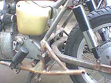
The engine and gearbox were then put into place so that I could work out the lengthwise location of the swinging arm . It then became obvious that in order to have the swinging arm pivot at the correct height , the back of the gearbox needed raising up . This was done by pivoting the engine about the bottom snubbers ( these being fixed points both in the engine and on the frame ) . It was achieved by moving the plate which carries the “Cobra” rubber from the back to the front of the frame lugs thus causing the gear box to move up in the frame by about 2 inches .
The bottom frame tubes were sprung apart ( about Ľ inch ) to line up with the support tubes and a cross tube welded in place , this tube carries a new mounting for the gearbox .
The top snubber fitted by simply sliding it forwards along the top tube .
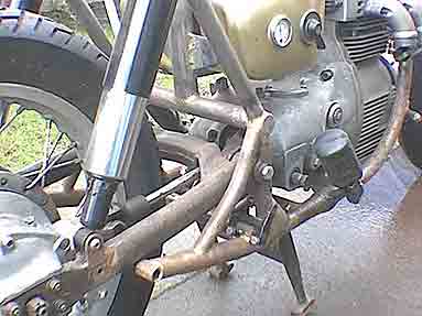
Then to connect the two ends of the frame , the swinging arm support tubes were fitted in place and welded at the meeting point of the frame and cross tubes . This was then made very rigid by extending the frame top tube backwards and down to another cross tube above the swing arm pivots .
A third cross tube was fitted forwards of the gearbox mounting to stiffen the bottom of the frame and to carry the centre stand more nearly at the centre of balance of the whole bike .
The new prop-shaft has a Sunbeam universal joint at the front and a Dneiper one at the rear , the shaft passes through an opening in the forward cross member of the swinging arm . This minimises movement at the sliding joint but does mean that every thing must be lined up very carefully to avoid contact between the shaft and the arm .
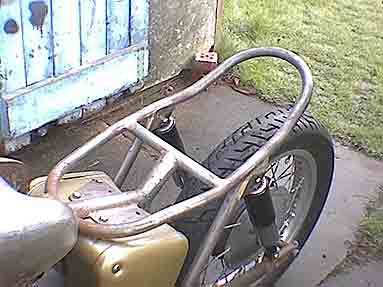
At this point in the build I ran into trouble when I tacked up a sub-frame and then tried to fit the dual seat , but these modern plastic based seats cannot be supported only at the two ends like a BSA one . I realised that I had to reverse the process by making a frame loop to closely fit the seat and then build this into the frame . Once I adopted this method the rear end of the frame was quickly finished , the spring units being a standard pair of Girlings as fitted to most of the heavier British bikes .
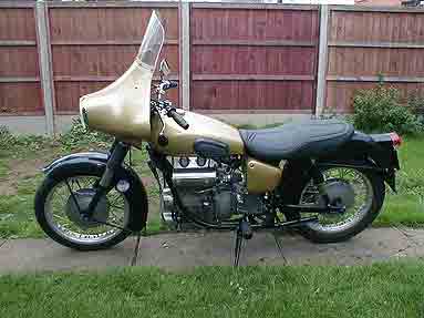
The electrical boxes are mounted in a similar way to on a Beam but spaced apart by the width of the frame top tube . Since the front of the seat is wider than a saddle this does not look out of place .
The cut out at the back of the petrol tank is filled in with a cover plate to blend in with the front of the seat , which I was informed comes from a Kawasaki “Zephyr”.
At the front the forks have been fitted with a set of taper roller steering head bearings which I modified myself from standard roller races .
All the front end , the headlight , mudguards , etc will be standard apart from the Dneiper brake . At the rear a fibreglass S8 mudguard will be suitably modified and mounted to fit in with the new suspension system .
As this is written the rear mudguard is the only major task which needs to be finished before the frame goes off for powder coating in blackest black . What I can’t make up my mind about is what colour to do the rest of the bike , black to look original or some bright colour to shout that it is different .