In the "Published Articles" section you will find Jim Readers method which is relatively straight forward .
My system which is rather more complicated and requires access to a machine shop is described below .
If anyone is really keen to try this e'mail me and I will send you the details .
Firstly like Jim I blanked off the feed to the main bearing , by removing the bearing
from the housing , pressing a short headed pin into the hole from the inside , then replacing the
bearing.
Next I machined up a new cover plate for the oil pump , this was the full width behind
the driving gear and extended out to the right , See Photo 1 .
Photo #1
By internal drill ways the oil is fed to a screwed in connector then down into the sump .
A flexible pipe ( braided high temperature hydraulic hose ) takes the oil towards the front of the engine , firstly to the pressure relief valve then out of the engine via a hollow bolt , see photo no 2 .
Photo #2
Two identical hollow bolts secure a circular oil filter carrier to the front of a Stewarts sump spacer , see photo no 3 .
Photo #3
Once the oil has been filtered it returns to the main bearing housing through another flexible pipe and a connector screwed into the original pressure relief valve housing . Leaving out the ball and spring of course .
Later on I altered the oil filter carrier to allow the fitting of a further pair of braided external pipes which carry the oil up to a large cooler just under the steering head , this makes a Sunbeam engine run much sweeter whether it be a standard one or the more powerful "Cross flow " as fitted to the "Sports Sunbeam" .
You my notice in photo no 2 , the plate which carries oil strainer looks different , this is the result of an earlier experiment to control the flow of oil inside the engine . It is my firm belief that although the oil drains at rest , once the engine is started , due to the presence of the flat plate supporting the strainer combined with the windage of the internal flywheel , most of the oil finishes above the plate going round with the crankshaft . T his explains why a Beam needs two oil control rings per piston and in some a small drop in the oil level sets the warning light flickering .
By raising the centre part of the plate almost up to the crankshaft and above the oil level , see photo no 4 , the oil is completely separated apart from a narrow collection area at each side .
Photo #4
For my money this idea works as I have always run my "Cross flow " using only the upper oil
control rings .
It occurs to me that a plate modified in this manner would probably provide enough room in the sump to fit a decent sized internal oil filter , possibly even without a sump spacer .
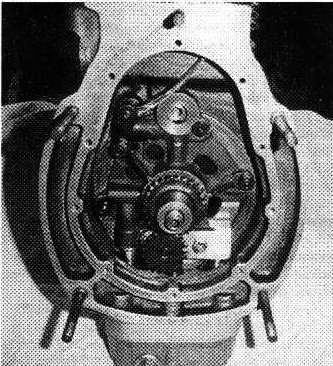 Photo #1
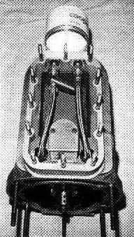 Photo #2
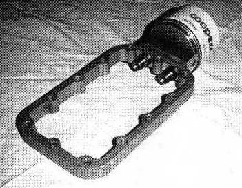 Photo #3
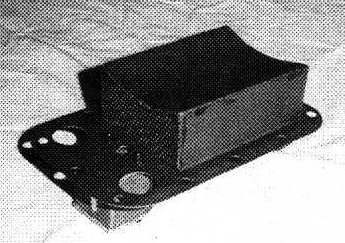 Photo #4